Electrical Checking/Testing
System Check With Volt/Ohmmeter
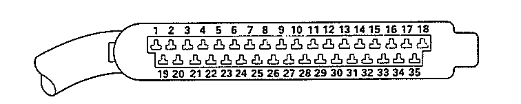
The entire A.F.C. System can be checked electrically at the control unit plug using an ohmmeter or volt meter according to the following chart.
Use this handy form to track your results.
OHMMETER TO TERMINAL |
SPECIFICATIONS |
CHECKS |
|
1 and Ground |
Disconnect white injection wire at coil ohms: hook wire to ground 0 ohms. |
Wire to #1 terminal on coil. |
|
3 and 18 |
Press accelerator pedal down fully. 0 ohms |
Full throttle enrichment circuit thru throttle switch. |
|
5 and Ground |
0 ohms |
Ground Circuit |
|
6 and 9 |
200-400 ohms |
Air Sensor Circuit |
|
6 and 8 |
130-260 ohms |
Air Sensor Circuit |
|
8 and 9 |
70-140 ohms |
Air Sensor Circuit |
|
6 and 7 |
40-300 ohms |
Air Sensor Circuit |
|
7 and 8 |
100-500 ohms |
Air Sensor Circuit |
|
6 and 27 |
Max. 2800 ohms at 68°F |
Air Sensor Circuit |
|
13 and Ground |
2100-2900 ohms at 68°F 270-390 at 176°F |
Head Sensor |
|
14 and 10 |
Approx. 7 to 9 ohms |
Injector wire and resistor |
|
15 and 10 |
Approx. 7 to 9 ohms |
Injector wire and resistor |
|
32 and 10 |
Approx. 7 to 9 ohms |
Injector wire and resistor |
|
33 and 10 |
Approx. 7 to 9 ohms |
Injector wire and resistor |
|
16 and Ground |
0 ohms |
Ground Circuit |
|
17 and Ground |
0 ohms |
Ground Circuit |
|
34 at control unit and 37 on the double relay |
Approx. 30 ohms |
Auxiliary air regulator and wires. |
VOLTMETER TO TERMINAL |
SPECIFICATIONS |
CHECKS |
|
4 and Ground |
Min. 9.5 volts during cranking 0 volts at all other times |
Signal from starter |
|
10 and Ground |
12 volts with key ON |
Voltage supply to computer |
|
20 and Ground |
12 volts with key ON and sensor flap open (or bridge terminal 36 to terminal 39 of air flow sensor plug) |
Pump Circuit |
control unit plug numbering